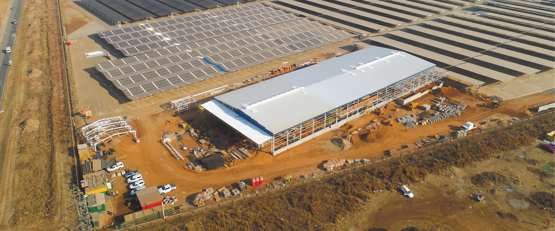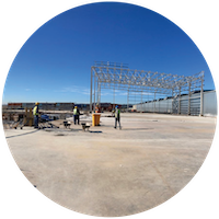
Existing Ford Silverton Assembly Plant invests R15-billion to advance technologies and build systems that modernise its Silverton Assembly Plant, taking production up to 200 000 annual vehicles (from a previous 168 000 vehicles produced). Expected to generate revenues exceeding 1.1% of South Africa’s gross domestic product, increasing domestic sales and exporting to over 100 global markets.
The plant is located in an industrial area on the outskirts of Silverton, the eastern suburb of Pretoria. The Silverton assembly plant currently overseas the production of the Everest and the Ranger Raptor.
Current square metre size of the Silverton plant is 296 596m2.
Press/Stamping Plant (1 783 tonnes steel; 173m x 62m; 10 726m2)
Body Shop (2287 tonnes steel; 240m x 145m; 34 800m2)
MP&L Warehouse (605 tonnes steel; 195m x 62m; 12 090 m2)

The stamping plant will use a high-speed line to produce all the major sheet metal components for the new Ranger bakkie and Volkswagen Amarok, starting in 2022. The line will contain 5 press machines (2500t, 1600t and 3 No. 1000t). Dies will be manoeuvred using 3 overhead cranes (2 No. 60 tonne capacity Slinger Cranes and 1 No. 63 tonne Gripper Crane) and one semi-gantry crane (50 tonne Slinger Crane), with possibility of adding a fourth 60 tonne overhead crane in the future. Will also house offices, CNC Mill, Blue Light Scanner Room and ATC training facility.
The design required for there to be 3 main overhead cranes to run alongside each other (with provisional design for a future crane added), as well as a semi gantry crane to run underneath these cranes. The higher cranes will run along 2 aisles (2 along each aisle), which adds to the complexity as the structure is required to resist combinations of lateral forces from the cranes and wind load.
Due to the large lateral forces and height of columns required, compound columns with custom I-sections (falling outside available typical sections) were designed to fall withing strength and deflection limits. The wind loading on the structure is higher on this plant than usual as the building is higher than typical Press Plants (23.5m high at the apex). Floor loading consists of heavy surcharge loads of 10t/m2 & 20t/m2 to be resisted by thick surface beds and retaining walls.

Building for assembling stamped plates and to build up car frames, containing the latest robotic technology.
The mechanical engineers required as much space inside the building as possible, which meant the plinths which support the internal columns had to be as small as possible to allow space for the equipment and machinery.
Any wind or lateral forces therefore were designed to be resisted by the external columns, as only these columns could have large enough plinths to have moment resisting base plates. This also provided the added benefit of not requiring any internal cross bracing for the structure, freeing up space and avoiding obstructions within the building.
The roof trusses are required to high equipment loads (incl. conveyors for partially complete cars and mezzanines), which required the capacity to support substructures connected eccentric to the truss nodes (intersection of section centrelines). This required the bottom chord of the trusses to resist both axial and potentially large bending forces.
After geotechnical testing and reports, it was found that some areas of the Body Shop could be supported on foundations, while majority had to be supported on a pile and pile cap system. Sacrifices were made by substituting previous design sections with available steel sections available (due to Covid-19).

Suspended storage facility to be used for storage, with basement extending full length of the suspended floor.
The warehouse floor is required to be connected to the Press Plant floor, which was at a higher level than the current ground level. This required a cost/benefit analysis between two options;
either the warehouse floor could be constructed to the required Press Plant floor level by backfilling with engineered fill and casting a surface bed, or design a suspended slab supported off a grid of columns, beneficially providing additional storage space (i.e. a basement).The suspended floor option was found to be a more beneficial option due to the increased utility for the building, while only marginally being more expensive than the backfill solution.
Careful construction planning was required such that convenient areas of the suspended warehouse could be used for storage as soon as possible and during construction. Due to the large length of the warehouse, the concrete elements required several expansion joints to mitigate cracking of the concrete, and shear walls to resist wind loading transferred for the propped steel warehouse.Due to poor soil conditions, the warehouse was also required to be supported on a pile and pile cap system. The piles were designed using a 2 pile per pile cap system, which resists overturning moments of the structure and economises the structure by alternating the orientation of the piles by 90 degrees, therefore requiring 2 piles per pile cap instead of 4 per pile cap.